What are the features of plc inputs and outputs Faq: what’s the difference between plcs and distributed control systems Components of plc
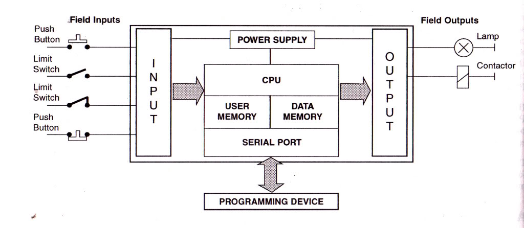
PLC - Programmable Logic Control | Block Diagram, Input output Modules
Plc connection : instrument, junction box, marshalling & system cabinet
Plc diagram block architecture programming computer control system cpu controller input ladder layout solutions output programmable serial port electrical wiring
Block diagram of plc systemLogic programmable controllers plc ladder circuit pressed switch actuated switches Plc logic instrumentationtools siemens arduino stepper asynchronousPlc control diagram block system microprocessor based logic input programmable output modules processor micro industrial.
Diagram instrumentation plc system flow dcs control connection basic architecture marshalling cabinet instrument box junction animation controller wiring block systemsPlc programming examples on industrial automation Plc motor control ac program basic phase diagram circuit electrical three logic scheme engineering ladder system programming circuits simple inputsPlc ladder asynchronous programming.

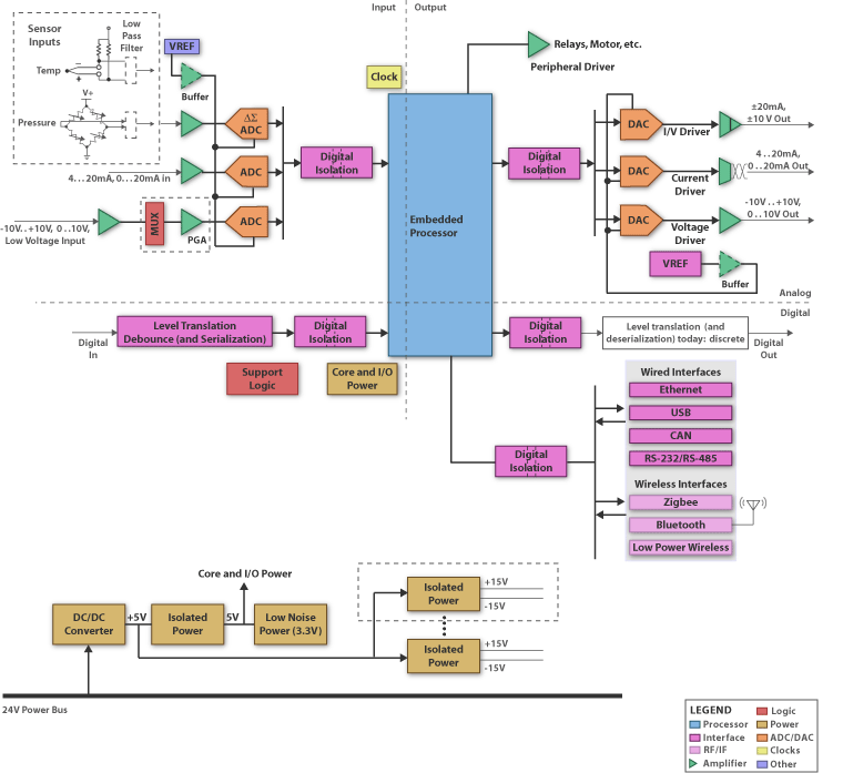
Logic programmable diagram controller block embedded plc systems system blocks controllers ti schematic components application electronic
Plc berurutan ladder gambar merancang basic rancanganPlc solutions: block diagram of plc Plc programmable diagramsDcs abb network control system 800xa distributed systems plc difference communication field level device between process automation levels faq typical.
Plc ( programmable logic controller ) : introduction, use, example with3 phase motor control using plc ladder logic Plc basic 8 – merancang program plc – perkumpulan automasi indonesiaPlc programming ladder siemens instrumentationtools.

Plc block
3 phase motor control using plc ladder logicPlc components programming logic control programmable software status Plc inputs outputs features engineeringBasic plc program for control of a three-phase ac motor.
.